Static Pressure Calculator
Enter the length, size and airflow of each duct segment and the fittings to see the friction, the fitting loss and the total pressure loss of the run.
Recent
Your last 10 settings, saved only in this browser. Nothing is uploaded.
How to use the Static Pressure Calculator
- Choose the airflow unit: cfm, L/s or m3/h. All segments share it. Results are in in. w.g. for cfm and in Pa for L/s or m3/h.
- Enter up to six segments. For each one, type the length (ft or m), the airflow, and the duct size (in or mm).
- For a rectangular duct, type width and height. For a round duct, type the diameter and leave height blank.
- Enter the number of elbows per segment. Type the elbow C once; the default of 0.3 is an example only, not from a table.
- For each segment, type the sum of any other loss coefficients. Use the coefficient for the real fitting from its maker or a design guide.
- Type any other losses (hood, filters, dampers, discharge) once, in in. w.g. or Pa.
- Check the duct material. Galvanized iron is set to 0.0005 ft. For a different roughness, choose “Other” and type it.
- If the air is not standard, open “More options” and set the air temperature and elevation. The defaults are 70 F and 0 ft.
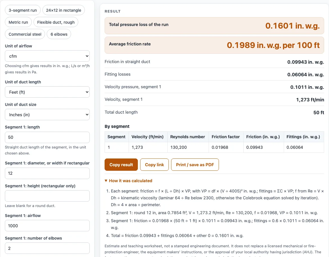
- Read the outputs: total pressure loss, average friction rate, friction, fittings, other losses, segment 1 velocity and velocity pressure, total length, and the table by segment.
- Read any warnings (Reynolds number, segment velocity, aspect ratio, totals above 10 in. w.g.).
The table by segment shows velocity, Reynolds number, friction factor, friction and fittings for each segment, so you can see which segment drives the loss.
How does a static pressure calculator add up the losses in a duct run?
The tool adds three kinds of loss: straight-duct friction, fitting losses and any other losses you type. Friction and fittings are summed over up to six segments, each with its own length, size and airflow, and the total is the pressure loss of the whole run.
Fitting losses use loss = C x VP, where C is the loss coefficient and VP is the velocity pressure of that segment. Each segment takes a count of elbows, all using the elbow C you type once, plus the sum of other coefficients you enter for that segment. Other losses are typed once in in. w.g. or Pa and added as typed.
What formula gives the friction loss in a straight duct?
Friction in each segment comes from the Darcy-Weisbach equation, dP = f x (L / Dh) x VP. Here L is the segment length, f is the friction factor, Dh is the hydraulic diameter and VP is the velocity pressure. Dh = 4 x area / perimeter, so a round duct uses its diameter, and a rectangular duct uses its width and height.
Velocity pressure is VP = df x (V/4005)^2 in in. w.g., with V in ft/min. Velocity is the airflow divided by the duct area, so a larger duct at the same airflow has a lower velocity and a lower friction loss.
How is the friction factor found for airflow in ducts?
The friction factor depends on the Reynolds number, Re = V x Dh / kinematic viscosity, and on wall roughness. Below Re 2300, the tool uses laminar flow, f = 64/Re, and roughness has no effect. Above that, it solves the Colebrook equation, 1/sqrt(f) = -2 log10[(e/Dh)/3.7 + 2.51/(Re sqrt(f))], by iteration. Viscosity comes from Sutherland’s law at the air temperature.
Roughness defaults to 0.0005 ft for galvanized iron, from a university fluid-mechanics table. Other listed values are 0.00015 ft for commercial steel or wrought iron and 0.000005 ft for drawn tubing, and “Other” accepts your own value. Sources differ on some points. Some references give a lower average roughness, 0.0003 ft, for round galvanized duct with longitudinal seams, and they place the laminar limit at 2000 or 2100 instead of 2300. The Colebrook results were checked against an independent solution and the textbook Moody example, where the chart gives 0.0225 and Colebrook gives 0.0222.
Worked examples
| Input | Result |
|---|---|
| 1000 cfm, 12 in, 50 ft | 0.1601 in. w.g. total, 0.199 in. w.g. per 100 ft |
| 3000 cfm, 24 x 12 in, 30 ft | 0.09924 in. w.g. total, 0.191 in. w.g. per 100 ft |
| 1000 cfm, 12 in, 85 ft | 0.2441 in. w.g. total, 0.189 in. w.g. per 100 ft |
| 500 L/s, 300 mm, 15 m | 47.49 Pa total, 1.96 Pa/m |
| 300 cfm, 8 in, 25 ft | 0.05583 in. w.g. total, 0.223 in. w.g. per 100 ft |
Calculated by the tool above; open it with the same values to see each step.
Frequently asked questions
Is the result a stamped engineering document I can submit?
No. The page is an estimate and teaching worksheet. It is not a stamped engineering document and does not replace a licensed engineer, the hood maker’s instructions or the authority having jurisdiction (AHJ).
Which elbow coefficient should I type?
Use the coefficient for the real fitting, from its maker or a design guide. The 0.3 in the tool is an example only, not from a table.
Which roughness value should I use for galvanized duct?
The default is 0.0005 ft from a university table. Some other references give 0.0003 ft for round galvanized duct with longitudinal seams, and 0.00027 to 0.0005 ft for rectangular galvanized. Type your own value with “Other” if you have a source for it.
Why does the tool show a warning?
Warnings appear for a Reynolds number from 2300 to 4000, where the friction factor is uncertain, and for a Reynolds number below 2300, where flow is laminar. Other warnings cover a segment velocity above 6,000 ft/min, an aspect ratio above 8:1, and totals above 10 in. w.g.
Does air temperature or elevation change the result?
Yes. Open “More options” to set the air temperature and elevation, which change the air density and viscosity. The defaults, 70 F and 0 ft, give standard air.
Why are my results in Pa instead of in. w.g.?
The units you choose set the output units. With cfm, results are in in. w.g. and the friction rate is in in. w.g. per 100 ft. With L/s or m3/h, results are in Pa and the rate is in Pa/m.
Related tools
- Ducts, Fans and Static Pressure: the hub for the duct, fan and pressure worksheets on this site.
- Duct Velocity Calculator: check the air velocity in a duct before you estimate its pressure loss.
- Grease Duct Velocity Calculator: velocity in a grease duct, with limits you type yourself.
- Commercial Kitchen Exhaust Fan Calculator: turn a total static pressure into brake horsepower and yearly energy.
- Exhaust Hood Calculator: open-face hood airflow, face velocity and opening size.
- Kitchen Hood CFM Calculator: total exhaust cfm for one or more commercial hoods.
- Commercial Kitchen Ventilation Worksheet: a printable worksheet with air balance and fan hp.